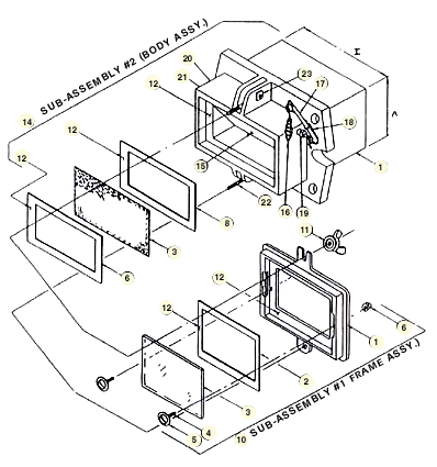
Proper installation and maintenance of our units is important to their quality, functionality, and longevity. SAF Viewports units are for use in low-pressure applications (5 PSI) where 100% shutoff is not required. Please find documentation available below for our various products.
Parts List

- 1 — Frame
- 2 — Frame Gasket*
- 3 — Glass*
- 4 — Truss Head Bolts (2 ea. per unit)
- 5 — Truss Head Gaskets (2 ea. per unit)
- 6 — Acorn Nuts (2 ea. per unit)
- 7 — Body
- 8 — Body Gasket (2 ea. per unit)*
- 9 — S.S. Screen*
- 10 — Sub-Assembly #1 – Frame Assembly
- 11 — Wing Nuts & Metal Washers (2 ea. per unit)
- 12 — Sealant*
- 13 — Mtg. Flange Gasket*
- 14 — Sub-Assembly #2 – Body Assembly
- 15 — Shutter
- 16 — Wire Drop Handle
- 17 — Handle Rod
- 18 — Torsion Spring
- 19 — Compression Fitting w. Packing
- 20 — Pipe Plug w. Nut
- 21 — Pipe Plug
- 22 — Eye Bolts
- 23 — Bolt w. Square Nuts*
*Indicates Recommended Spare Parts
Sub-Assembly Instructions
Sub-Assembly #1 – Frame Assembly
- Apply 1/8″ bead of sealant (12) to interior lip of frame (1).
- Place frame gasket (2) onto sealant (12).
- Repeat with 1/8″ bead of sealant (12).
- Position glass (3) into place on sealant (12).
- Position truss head gaskets (5) over holes in the interior of frame (1) & place truss head bolts (4) thru holes.
- Place acorn nuts (6) over truss head bolts (4) on exterior of frame (1) & tighten with extreme care or glass may break.
Sub-Assembly #2 – Body Assembly
- Apply 1/8″ bead of sealant (12) to interior lip of body (7).
- Place gasket (8) onto sealant (12).
- Repeat with sealant(12).
- Place screen (9) onto sealant (12).
- Place gasket (8) onto screen (9).
- Repeat with sealant (12).
- Place assembled frame (10) onto sealant (12).
- Position metal washers & wing nuts (11) in place & tighten.
View Port Installation Instructions
- Cut a hole in furnace wall approx. 1/8″ larger than the A & I Dimensions.
- Position studs provided by customer.
- Place flange gasket (13) to flange on rectangular view port (E Dimension).
- Insert into furnace wall opening.
- Securely tighten nuts on studs.
- See catalog dimension sheet for stud location & furnace wall hole dimensions.
View Port Maintenance
- Cleaning or replacing of glass can be done while the equipment is in operation.
- To clean the interior of the glass, the frame (10) must be removed from the body (14) of the rectangular view port.
- Once this is done, the rectangular view port is no longer considered pressure-tight.
- We recommend following the Sub-Assembly Instructions procedure for both #1 and #2 Sub-Assemblies (as shown above) before the equipment is put back in to operation.

